|
|||
 How does it work
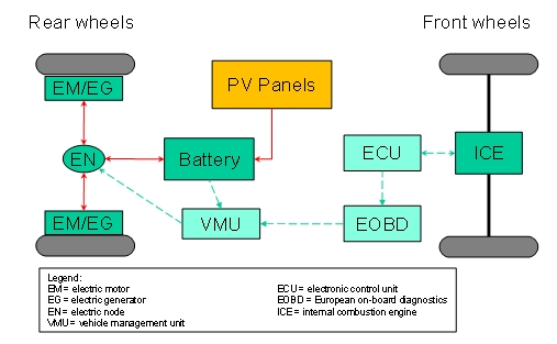
The above figure shows a block diagram of the mild hybrid solar vehicle. The hybridizing equipment is installed on a conventional car (two front wheels drive), in which the front wheels are propelled by the Internal Combustion Engine (ICE) controlled by an Engine Control Unit (ECU). The vehicle is also equipped with an EOBD gate (On Board Diagnostics protocol), which allows accessing data such as pedal position, vehicle speed, engine speed, manifold pressure and other variables. A mild parallel hybrid structure is obtained by substituting/integrating the rear wheels with in-wheel motors. In that way, the vehicle can operate in pure electric mode (when ICE is switched off or disconnected by the front wheels) or in hybrid mode (when the ICE drives the front wheels and the rear in-wheel motors operate in traction mode or in generation mode, corresponding to a positive or negative torque). The battery can be recharged both by rear wheels, when operating in generation mode, and by photovoltaic panels. The Vehicle Management Unit (VMU), which is part of the invention and implements control logics compatible with typical drive styles of conventional-car users, receives the data from OBD gate, from battery (SOC estimation) and drives in-wheel motors by properly acting on the electric node EN. A display on the dashboard may advice the driver about the actual operation of the system. The KitThe kit of equipments, to be installed for converting a conventional car into a hybrid solar vehicle, will include:
|

|